When a device interrupts the processor, a number of things occur. First, the task currently being run by the processor is suspended while the processor handles the interrupt. Second, a procedure, known as an interrupt handler (or interrupt service routine), must be activated. The interrupt handler is responsible for servicing the interrupt (that is, determining why the interrupt has occurred and what to do about it). Third, the suspended task must be resumed once the interrupt handler is finished.
In the case of the 80x86 processors, when an interrupt occurs, the task currently executing is suspended by pushing the instruction counter and the status flag on the stack, thereby permitting control to be returned to the task once the interrupt has been serviced. To ensure that no further interrupts will occur during the handling of the first interrupt, the 80x86 processor disables interrupts (i.e., if other interrupts occur, they are blocked until the processor either explicitly enables interrupts or resumes execution of the interrupted task).
Each device on the PC is associated with a interrupt request number or IRQ:
| IRQ | Device |
|---|---|
| 0 | Clock |
| 1 | Keyboard |
| 2 | From slave 8259 |
| 3 | Serial Port 2 |
| 4 | Serial Port 1 |
| 5 | Hard Disk |
| 6 | Floppy Disk |
| 7 | Printer |
The lower the IRQ value, the higher the priority. For example, the clock (IRQ0) has higher priority than does the hard disk (IRQ5).
When an interrupt occurs, the interrupting device's IRQ is added to a constant that is the device's interrupt number. The interrupt number refers to the device's interrupt vector stored in segment zero. The constant can be any multiple of 8 (0, 8, 16, 24, and so forth); since the first few vectors are used for CPU exceptions, IBM and Microsoft chose the value of the constant to be 8.
The following table shows the assignment of interrupt numbers by IBM and Microsoft, interrupt vector locations, and the eight 'standard' devices (note that there is no obvious relationship between the ports associated with a device and the device's interrupt number):
| Interrupt Number | Interrupt Vector Location | Device |
|---|---|---|
| 0x08 | 0x20 - 0x23 | Clock |
| 0x09 | 0x24 - 0x27 | Keyboard |
| 0x0A | 0x28 - 0x2B | From slave 8259 |
| 0x0B | 0x2C - 0x2F | Serial Port 2 |
| 0x0C | 0x30 - 0x33 | Serial Port 1 |
| 0x0D | 0x34 - 0x37 | Hard Disk |
| 0x0E | 0x38 - 0x3B | Floppy Disk |
| 0x0F | 0x3C - 0x3F | Printer |
When a device causes an interrupt, the instruction counter is assigned the value of the device's interrupt vector. Control is then passed to the interrupt handler. Once the interrupt has been serviced, the stack is popped, restoring the original task's instruction counter and status flag. Interrupts are reenabled because the interrupt enable bit is set in the status flag.
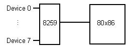
Although the 8086 processor is designed to handle up to eight external devices, there is only a single interrupt line connecting the processor to the outside world, meaning that without some form of additional hardware, at most one external device can be connected to the processor. Fortunately, hardware such as the Intel 8259 Interrupt Controller has been designed to share the single interrupt line between eight different devices. The following figure shows the relationship between the devices, the 8259, and the 80x86 processor.
This means that instead of interrupting the processor directly, a device first signals the 8259, which then interrupts the 8086 processor using the single interrupt line. The processor determines which device is interrupting by obtaining the device's number from the 8259. The 8086 processor uses the device number to access the list of interrupt vectors that indicates which interrupt handler should be activated.
The 8259 permits the programmer to select those devices which are to interrupt the 8086 processor by writing a one-byte interrupt mask to the 8259. Each bit in the mask corresponds to one of the eight devices. Device priority is indicated from right to left, with the clock having the highest priority and the printer, the lowest:
| Priority | 8259 Bit | Device |
|---|---|---|
| Highest | 0 | Clock |
| 1 | Keyboard | |
| 2 | From slave 8259 | |
| 3 | Serial Port 2 | |
| 4 | Serial Port 1 | |
| 5 | Hard Disk | |
| 6 | Floppy Disk | |
| Lowest | 7 | Printer |
A bit value of one in the interrupt mask indicates that any interrupts coming from the device are to be ignored, while a bit value of zero means that the device is allowed to interrupt the 8086. For example, to permit clock, keyboard, and printer interrupts, the interrupt mask would be set to 0x7C.
The 8259 interrupt mask is accessed through port 0x21, the interrupt mask register. The above example could be implemented as follows:
#define INT_MASK   0x21
#define CLKENA     0xFE   /* Clock enable:    11111110 */
#define KEYENA     0xFD   /* Keyboard enable: 11111101 */
#define PRTENA     0x7F   /* Printer enable:  01111111 */
...
outportb(INT_MASK, CLKENA & KEYENA & PRTENA);
For each device that is selected, there must be a corresponding interrupt handler and the interrupt vector associated with the device must contain the entry point of the interrupt handler. Results will be unpredictable if either the interrupt handler is missing or the interrupt vector contains an invalid entry point, since control will be passed to a location that does not service the interrupt.
If several devices interrupt simultaneously, the 8259 signals the processor with the highest priority interrupt. All other devices (with lower priority interrupts) are kept waiting. The keyboard interrupt has the highest priority of all the other devices (except the clock) to ensure that special sequences such as Ctrl-Alt-Del are not blocked. The interrupt handler should be kept as short as possible since all interrupts are blocked while the interrupt handler is active unless the interrupt handler explicitly enables interrupts. An unduly long interrupt handler can result in interrupts being lost. Once the interrupt has been serviced, the 8259 must be informed so that any pending (or any subsequent) interrupts can be signalled. This is done by writing EOI (end-of-interrupt, a value of 0x20) to the 8259 Operation Command Word register (port number 0x20):
#define EOI    0x20
#define OCW    0x20

void interrupt isr()
{

...

/* Acknowledge interrupt */
outportb(OCW, EOI);
}
It does not matter where interrupts are acknowledged, since CPU interrupts are blocked at this time. When control leaves the ISR, the next pending interrupt (if there is one), will occur. Conversely, if the 8259 is not acknowledged, no further interrupts will be made available.
© 2006 - Whale Lake Press