Before a computer can communicate with a user or another computer, it requires:
This document examines some of the hardware supplied with a typical PC and considers the software required to control the hardware.
The 8086 is the generic name given to a family of microprocessors developed by Intel and supplied with personal computers such as the IBM PC and its clones. At present, there are some six members of this family that can support OSLab:
For the most part, all members of the 8086 family are upwardly compatible, meaning that software developed for an earlier version of the processor should be able to run on a later one.
Although recent versions of the 8086 family (such as the 80486) are more powerful than earlier ones (such as the 8086), the mechanisms whereby the external hardware (or devices) is accessed have essentially remained unchanged, once again, to allow the upward compatibility of software.
Information is supplied to and received from an 8086 processor through devices such as the keyboard, screen, disk, light-pen, serial port, and mouse. Although there seems to be a limitless supply of possible devices that can be attached to a PC, the standard PC configuration generally allows only eight (typically, the clock, keyboard, screen, hard disk, floppy disk, printer, and two serial communication interfaces). AT configurations allow a total of fifteen devices.
Devices are not accessed directly (as, for example, memory is); instead, an 8086 processor accesses a device through one or more ports. To ensure that the PC can distinguish between them, all devices are assigned one or more unique port numbers. Although only a limited number of devices can be attached at any one time, there are some possible ports available on the PC. The number of ports associated with a device depends, in part, upon the number of functions it performs. For example, the clock is associated with four ports, while the keyboard uses two.
Ports can be accessed through software using two 'low-level' instructions. The in instruction allows a port to be read, while a port can be written to using the out instruction. The in instruction accepts a port number and returns the value (a byte) associated with that port, while the out instruction requires both a port number and the byte to be written to the device. The 'high-level' Borland C/C++ counterparts of these instructions are:
The types of operation (i.e., reading or writing) that can be performed on a port depend upon the functions of the device that the port supports. For example, some ports, such as the input buffer associated with the keyboard (port number 0x60) are to be read; while others, such as the clock command register (port number 0x43), used for programming the clock, are for writing. Finally, some ports can be both written to and read from. For example, the keyboard status register (port number 0x61) can be read (to obtain the status of the keyboard) and written (to signal the keyboard that the supplied character has been accepted).
Of the eight 'standard' devices that can be supported by a PC, only two are of direct interest at this moment: the keyboard and clock, since they are both used by OSLab.
The keyboard is an input device that allows a user to supply information to the processor in alpha-numeric format. The number of keys on the keyboard and their layout depends upon the type of PC and the keyboard's manufacturer.
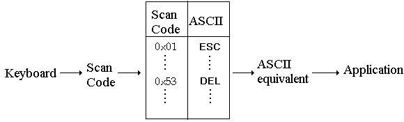
Although the 8086 processor uses the ASCII character code, the PC keyboard does not generate ASCII characters; instead, each character on the keyboard is associated with a one-byte scan code. The scan code is returned to the processor via port 0x60.
IBM has defined a scan code for each key (to remain compatible with the IBM PC; keyboards built by other manufacturers must generate scan codes that correspond to those found on the IBM PC, regardless of where the keys are placed on the keyboard). For example, the Escape key (Esc) generates scan code 0x01, while the Delete key (Del) generates scan code 0x53. Since the value of the scan codes do not correspond to a specific character code (such as ASCII or EBCDIC), the scan code must be translated into the character code required by the application. The translation is done through software within the processor, mapping the scan code into the equivalent character code character, typically using a translation (or mapping) table as shown in the following figure:
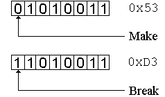
The processor is signalled twice whenever a key is touched: once when the key is pressed (generating the make scan code), and once when the key is released (generating the break scan code). Regardless of whether the scan code is a make or a break, the lower seven bits of the scan code identify the key. The eighth bit is cleared by the keyboard to indicate a make and is set to signal a break. For example, in the following figure, the make scan code for the Delete key (generated when the Del key is pressed) is 0x53, while the break scan code (generated when the Del key is released) is 0xD3.
The keyboard can generate 127 different scan codes (with values 1 through 127). Scan code 0x00 is reserved to allow the keyboard to expand to more than 127 characters. Keys outside the 127 character range are sent as two scan codes, 0x00 and the scan code of the key. If the keyboard is equipped with an 'auto-repeat' feature (that is, when a key is held down, the keyboard eventually starts to repeat the character), the keyboard sends each character as a make, then as a break, eliminating the need for the user to continuously press and release the same key. The keyboard is also equipped with a 16-byte buffer for storing scan codes until they are read by the processor.
The keyboard software obtains the scan code by reading port 0x60. It must then signal the keyboard that the character has been read; a seemingly convoluted process involving the following steps:
The 'flip' of the high-order keyboard status bit signals that the scan code has been read, thereby allowing the keyboard to remove the scan code from the keyboard buffer. An algorithm that converts all scan codes into a single case (i.e., all upper or all lower) can be implemented by ignoring any incoming 'make' scan codes, and processing the 'break' scan codes only:
The above algorithm is limited in that it supports a single case and doesn't permit control characters. Fortunately, the make/break cycle allows a program to determine which keys have been pressed and the order in which they have been pressed, thereby permitting the keyboard software to distinguish between sequences such as 'A-Shift', 'Shift-A', or even 'Shift (release) A'. For example, the key designated 'A' on the keyboard can generate one of a number of ASCII values, depending upon the other keys that have been pressed beforehand and how the software interprets the sequence of keys being pressed (note that the keyboard distinguishes between left and right Shifts, and that Ctrl is an abbreviation of Control). Various key combinations are shown in the following table:
| First Key | Second Key | Third Key | Result | ASCII Value |
|---|---|---|---|---|
| A | 'a' | 0x61 | ||
| Shift Left | A | 'A' | 0x41 | |
| Shift Right | A | 'A' | 0x41 | |
| Ctrl | A |
 | 0x01 | |
| Altmode | A | ß | 0xE1 | |
| Altmode | Shift | A |
 | 0xC1 |
| Ctrl | Altmode | A | ü | 0x81 |
If multiple keys are pressed (for example, to obtain a capital letter, a control character, or a special sequence such as Ctrl-Alt-Del), the keyboard software must maintain state information about these keys since the scan codes are supplied to the processor one-at-a-time. At a minimum, the keyboard software should be able to 'remember' whether the Ctrl, Altmode, Left Shift, and Right Shift keys have been pressed. The state of any of these keys can be maintained as a boolean condition (a key is either pressed or it isn't), with the initial state of each key being FALSE. Whenever one of these keys is pressed (i.e., the make scan code), the state can change to TRUE, and when the key is released (i.e., the break scan code), the state can change to FALSE.
This also means that two mapping tables are required, one for unshifted characters, and the other for shifted characters. There is not necessarily a one-to-one correspondence between the tables (for example, 'a' to 'A'), since some unshifted characters don't have a shifted equivalent (such as '1' and '~').
ASCII control characters are those less than 0x20 (space) and can be obtained by ANDing the character with <>0x1F. Similarly, altmode characters are those greater than 0x7F (Del) and are generated by or'ing the character with 0x80.
The clock (or more correctly, the 8253 timer chip) is used to supply the PC with a regular, periodic clock pulse that can be used to control various actions. The 8253's three independent timing channels that are used by the PC are shown in the table below:
| Channel | Function |
|---|---|
| 0 | System timing and counting |
| 1 | Memory refresh (via DMA controller) |
| 2 | PC speaker (for sound effects) |
Of the three channels, channel 0 can be used by programs (such as MS-DOS and Commkit) as a mechanism to control hardware and software access to the PC. Channel 1 must not be changed, since this can result in the loss of the contents of the PC's memory. Channel 2 is not used by Commkit.
Internally, the 8253 has a 1.19318 MHz clock which supplies each timing channel with 1,193,180 clock pulses each second. Since most applications do not require this accuracy of timing, each channel is associated with a programmable 16-bit counter that can be decremented by the timer chip on each clock pulse. When the counter reaches zero, the application can be informed. As an example, assume that an application requires the clock to signal the processor 1000 times a second (in other words, once a millisecond). The counter must be initialized to a value that will reach zero after one millisecond has passed. Dividing the clock speed (1,193,180) by 1000 gives 1,193; setting the counter to 1,193 results in the counter reaching zero after approximately one millisecond.
The 8253 clock is associated with four ports. Ports 0x40, 0x41, and 0x42 are known as the clock counter registers and are used to supply the initial clock values to channels 0, 1, and 2, respectively. The clock command register (port 0x43), allows the programmer to specify how a clock is to be used as well as how the clock is to be initialized. For example, once a clock's counter reaches zero, the clock can be programmed to load itself with the original counter value (stored in the clock latch) and repeat the cycle. Alternately, it can be programmed to stop at zero (this is known as single-shot mode). Similarly, the value loaded into the clock latch (through the clock counter register) can be the full 16 bits (obtained by writing the low-order and then the high-order byte to the clock counter register), or simply half of the clock value (i.e., either the low-order or the high-order byte).
Although a device can be accessed at any time (through one or more of its ports), it is not always advisable to do so. For example, the keyboard register can be read, regardless of whether or not the user has typed a character. Accessing a device before it is ready can result in the duplication of information (reading the serial communication interface more than once before a new character has arrived will result in a copy of the original character being returned), or the loss of information (writing to the serial communication interface before the last character has been sent can result in the new character overwriting the previous character). To avoid situations in which data is lost or duplicated, most devices are able to signal their status to the processor. Typically, the status indicates whether the device has information for the processor or is ready to accept more information.
The status of the device can be obtained either by the processor polling the device or by having the device interrupt the processor.
The state of a device can be obtained by reading one or more ports associated with the device. For example, it is possible to configure the clock so that it counts down to zero and stops. By polling the port associated with the clock, a program can determine whether the clock has reached zero.
Device polling is a simple and sometimes convenient mechanism whereby a program can determine the status of a device. Software for device polling is typically written as a loop known as a polling loop:
for(;;)
{
   if (device1_ready()) service_device_1();
   if (device2_ready()) service_device_2();
}
There are, however, at least two drawbacks to using device polling: first, the processor performs no useful function other than polling; and second, if a device happens to generate data faster than it takes the processor to execute the polling loop, data can be lost. For example, consider the following polling loop:
for(;;)
{
   if (device1_ready()) service_device_1();
   if (device2_ready()) service_device_2();
   if (device3_ready()) service_device_3();
   if (device4_ready()) service_device_4();
}
If device1 supplies data faster than it takes the processor to check each device in the polling loop, there is a possibility that data from device1 could be lost. A common trick that can be employed to overcome this problem is to poll the fast device more than once in the polling loop.
Ideally, what is required is a mechanism whereby the processor is signalled only when a device needs to be serviced or the device has information to supply to the processor. This allows the processor to perform tasks other than device polling (for example, a user can type information at a keyboard while other information is being written to a disk). Most processors, including those in the 8086 family, allow devices to signal or interrupt the processor when a condition has been reached, thereby overcoming the limitations associated with device polling. For example, instead of the software polling a disk to determine if a block of data has been written, the disk itself can inform the software that the data has been written.
When a device interrupts the processor, a number of things occur. First, the task currently being run by the processor is suspended while the processor handles the interrupt. Second, a procedure, known as an interrupt handler (or interrupt service routine), must be activated. The interrupt handler is responsible for servicing the interrupt (that is, determining why the interrupt has occurred and what to do about it). Third, the suspended task must be resumed once the interrupt handler is finished.
In the case of the 8086 processors, when an interrupt occurs, the task currently executing is suspended by pushing the instruction counter and the status flag on the stack, thereby permitting control to be returned to the task once the interrupt has been serviced. To ensure that no further interrupts will occur during the handling of the first interrupt, the 8086 processor disables interrupts (i.e., if other interrupts occur, they are blocked until the processor either explicitly enables interrupts or resumes execution of the interrupted task).
Each device is associated with a unique interrupt number that the processor obtains when the interrupt occurs. The interrupt number is used as an index into the list of interrupt vectors stored in segment zero. The following table shows the assignment of interrupt numbers, interrupt vector locations, and the eight 'standard' devices (note that there is no obvious relationship between the ports associated with a device and the device's interrupt number):
| Interrupt | Interrupt | Device |
|---|---|---|
| Number | Vector Location | Device |
| 0x08 | 0x20 - 0x23 | Clock |
| 0x09 | 0x24 - 0x27 | Keyboard |
| 0x0A | 0x28 - 0x2B | From slave 8259 |
| 0x0B | 0x2C - 0x2F | Serial Port |
| 0x0C | 0x30 - 0x33 | Serial Port |
| 0x0D | 0x34 - 0x37 | Hard Disk |
| 0x0E | 0x38 - 0x3B | Floppy Disk |
| 0x0F | 0x3C - 0x3F | Printer |
When a device causes an interrupt, the instruction counter is assigned the value of the device's interrupt vector. Control is then passed to the interrupt handler. Once the interrupt has been serviced, the stack is popped, restoring the original task's instruction counter and status flag. Interrupts are reenabled because the interrupt enable bit is set in the status flag.
Although the 8086 processor is designed to handle up to eight external devices, there is only a single interrupt line connecting the processor to the outside world, meaning that without some form of additional hardware, at most one external device can be connected to the processor. Fortunately, hardware such as the Intel 8259 Interrupt Controller has been designed to share the single interrupt line between eight different devices. The following figure shows the relationship between the devices, the 8259, and the 8086 processor:
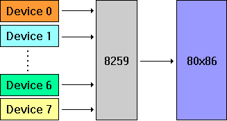
This means that instead of interrupting the processor directly, a device first signals the 8259, which then interrupts the 8086 processor using the single interrupt line. The processor determines which device is interrupting by obtaining the device's number from the 8259. The 8086 processor uses the device number to access the list of interrupt vectors that indicates which interrupt handler should be activated.
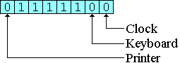
The 8259 permits the programmer to select those devices which are to interrupt the 8086 processor by writing a one-byte interrupt mask to the 8259. Each bit in the mask corresponds to one of the eight devices. As shown in the following figure, device priority is indicated from right to left, with the clock having the highest priority and the printer, the lowest:
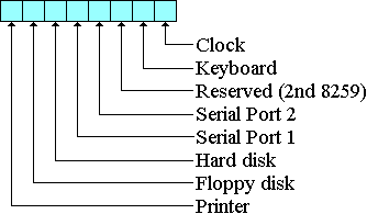
A bit value of one in the interrupt mask indicates that any interrupts coming from the device are to be ignored, while a bit value of zero means that the device is allowed to interrupt the 8086. For example, to permit clock, keyboard, and printer interrupts, the interrupt mask would be set to 0x7C, as shown in the following figure:
The 8259 interrupt mask is accessed through port 0x21, the interrupt mask register. The above example could be implemented as follows:
#define INT_MASK   0x21
#define CLKENA     0xFE   /* Clock enable:    11111110 */
#define KEYENA     0xFD   /* Keyboard enable: 11111101 */
#define PRTENA     0x7F   /* Printer enable:  01111111 */
...
outportb(INT_MASK, CLKENA & KEYENA & PRTENA);
For each device that is selected, there must be a corresponding interrupt handler and the interrupt vector associated with the device must contain the entry point of the interrupt handler. Results will be unpredictable if either the interrupt handler is missing or the interrupt vector contains an invalid entry point, since control will be passed to a location that does not service the interrupt.
If several devices interrupt simultaneously, the 8259 signals the processor with the highest priority interrupt. All other devices (with lower priority interrupts) are kept waiting. The keyboard interrupt has the highest priority of all the other devices (except the clock) to ensure that special sequences such as Ctrl-Alt-Del are not blocked. The interrupt handler should be kept as short as possible since all interrupts are blocked while the interrupt handler is active unless the interrupt handler explicitly enables interrupts. An unduly long interrupt handler can result in interrupts being lost. Once the interrupt has been serviced, the 8259 must be informed so that any pending (or any subsequent) interrupts can be signalled. This is done by writing EOI (end-of-interrupt, a value of 0x20) to the 8259 Operation Command Word register (port number 0x20).
From: Introduction to Data Communications: A Practical Approach by Larry Hughes (Jones and Bartlett, 1997)